
The Scarab Grand Prix engine
Author
- Ron Rex
Date
- March 5, 2020
Related articles
- Scarab - Grand Prix roadster, by Don Capps
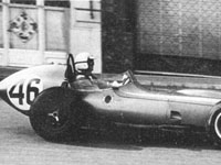
Who?Chuck Daigh What?Scarab GP-1 Where?Monte Carlo When?XVIII Monaco GP (May 29, 1960) |
 |
Why?
1 - The Era
1960 was the final year of the 2.5-litre un-supercharged Grand Prix formula (that had run since 1954) and the Drivers' and Constructors' Championships were won that year by respectively the Australian driver Jack Brabham and the Cooper Car Co. Ltd. with its rear or mid-engined Cooper Climax car, as they had the year before.
Lotus and BRM had also produced rear-engined cars for the 1960 season and even Ferrari had built one, entering it alongside their front-engined cars to gain experience for a change to that configuration for its cars for 1961. Aston Martin laboured on with its front-engined car, albeit in revised form.
This effectively signalled the end of the dominance of the traditional front-engine configuration Grand Prix car that had reigned since GP racing began, except for a notable number of successes by the rear-engined Auto-Unions in the 1930s.
Inopportunely, 1960 also saw the delayed entry of the American Scarab GP team with their front-engined car which would prove to be totally outclassed by the new rear-engined cars that it now had to compete against. The Scarab was manufactured by Reventlow Automobiles Inc., a company set up by young American, Lance Reventlow, to fulfil his desire to produce American racing cars to compete on the world stage.
2 - Background
Lance Reventlow was the wealthy son of Woolworth heiress Barbara Hutton, who financed her son's motor racing activities. When he started driving racing cars in 1955, he turned to experienced Californian Warren Olson to prepare them for him. Olson had trained as a Naval aviation machinist in WW2, had set up a race car preparation shop in the North-West of Los Angeles in 1952 and was an agent for Cooper Cars.
In 1957, at the age of 21, Reventlow and friend Bruce Kessler had gone to Europe to compete in motor races, Reventlow racing a 200S Maserati and a 1500cc SOHC Formula 2 Cooper-Climax without any success (prepared by Warren Olson who accompanied them). While there, Reventlow and Kessler visited the European racing car manufacturers Ferrari, Maserati and OSCA (at Maserati, Reventlow purchased one of their FIAT transporters for his own use). They then went on to England where they visited Lotus, Cooper and BRM, finishing up at Brian Lister's workshop in Cambridge. Reventlow had intended to purchase a Lister chassis and fit a Chevrolet V8 for the following years World Championship Sports Car season, but he was not impressed with what he saw and felt that he could have a better car produced in America, so he resolved to set up a factory to produce a team of his own sports racing cars.
Returning to America with Olson in August 1957, Reventlow had his attorney Stan Mullin set up the legal framework for his new company, Reventlow Autombiles Inc. (RAI) which would allow him to write off losses as tax offsets for up to five years while he pursued his dream.
Reventlow set about hiring experienced people who worked in the motor racing hub of the Los Angeles area (many with a background in the aviation industry) to design and build his cars which he named Scarab, the name of an Egyptian symbol of immortality or as Reventlow sometimes jokingly said, also that of a dung beetle.
The first employee was the trusted Warren Olson in the position of general manager and he was to run the Scarab programme from start to finish.
RAI set up in three bays of Olson's shop which had recently been relocated to Robertson Boulevard, West Hollywood, in Los Angeles.
Olson in turn hired Dick Troutman and Tom Barnes to build the Scarabs. They were skilled fabricators who had recently been working at Kurtis-Kraft of Indy fame. He then hired Chuck Daigh, a gifted mechanic, to develop the Chevrolet 283cu in 'small block' pushrod OHV V8 that Reventlow wanted to use. Daigh was also to be a driver.
3 - The Sports Racing Cars
Design of the Scarab sports cars started in August 1957. The Chevrolet V8 was modified, its capacity eventually increased to over 5.5 litres and fitted with an modified form of Hilborn fuel injection. The car incorporated virtually all American-sourced components and was designed to be suitable for international road racing. It was built to a very high engineering standard with a De Dion rear axle and embodied all the experience of the new team's members. The intention was to enter the cars in the World Sports Car Championship in 1958, but in September the FIA unexpectedly announced that the current unlimited engine capacity that was allowed was to be replaced with a maximum capacity of 3 litres starting in 1958. This ruled the Scarabs out but Reventlow decided to continue developing the Chevrolet V8 and forgo European racing for the time being while he considered his options.
The first car, the MkI, was completed in February 1958 but it was found that more space was needed for the burgeoning Scarab project, as Olson was still running his race preparation service from the same shop. So RAI moved into Jim Nairn's well-equipped workshop at 11930 South Jefferson Boulevard, Culver City, Los Angeles in the early summer of 1958.The next two MkII sports cars were built there, as would the future Grand Prix cars.
Next door, at number 11928 South Jefferson Blvd., was TRACO Engineering run by the experienced engine builders Jim Travers and Frank Coon and they were engaged by Olson to help develop the Chevrolet engine. Many others joined RAI as the team grew, including Phil Remington to oversee the building of the cars (and who would go on to have a major role in the Ford GT40 project).
Reventlow still wanted to compete on the world stage with his sports cars and the only likely American engine option under the new rules was the 220 Offenhauser 4-cylinder track racing engine in 3-litre (183cu in) form. So in January 1958 Daigh purchased one on behalf of RAI and Travers and Coon were tasked with adapting it to run on petrol for road racing to see if it was suitable, while the Chevy V8 engines were developed and raced. But the Offenhauser wasn't a success, it was too heavy, down on power and lacked flexibility. Reventlow realised if he was going to race his cars in European events he would need a purpose-built racing engine. The Offy was only tried once in the sports cars (chassis 003) in September 1958 and failed to finish.
The V8 Scarab sports racing cars were entered in the Sports Car Club of America (SCCA) series of races in 1958 and proved overwhelmingly dominant, beating the best of European sports racing cars competing in the series, including Maserati 450S V8s and the Ferrari 412MI V12. This success further bolstered Reventlow's confidence in the ability of his American team and he decided to build a Grand Prix car to compete in the final two years of the FIA 2.5-litre Formula 1. After triumphing at the Nassau races in December 1958, Reventlow announced that he was retiring the race-winning car to be converted for street use and putting the other two Scarabs up for sale, the proceeds going to help fund his all-American GP car project.
4 - The Grand Prix Car
Reventlow had decided to build a Grand Prix car early in June 1958 so, while the triumphant sports car season was getting into full swing, work was also put in hand on the GP car's design and in the recruitment of the necessary personnel. The car was to be all-American in design and composition and this was the first problem as at this period in time there was little to no American experience in designing and building a F1 Grand Prix car.
After interviewing several candidates, Olson hired Marshall Whitfield, a young aircraft engineer working for the Douglas Aircraft Company, to design the chassis and suspension. The car was of traditional concept, a space frame, front engine/rear drive with independent suspension all round. The engine was to be mounted in a very laydown position with the crankshaft on the left, so that the driveshaft and gearbox could be located beside the driver, allowing a low seating position.
Herein was the next of RAI's problems, for earlier that year the opening two Grands Prix had been won by rear-engined Cooper-Climax cars, signalling a dramatic change in racing car design. Reventlow himself had raced rear-engined cars, a Cooper T39 'Bobtail' sports racer in 1956 and a F2 Cooper-Climax FWB T43 MkII in 1957 and 1958. RAI did consider a rear-engine layout but opted for the apparent simplicity of a front-engine layout and Reventlow was to admit in later years that he should have seen the writing on the wall, based on his own experience.
In line with using all-American components, the gearbox was an RAI casing with Chevrolet Corvette 4-speed gear sets and a supplementary casing incorporating a starting gear and reverse, built up by mechanic 'Sonny' Balcaen who had previously worked for Olson and then Jim Hall. Reventlow at first wouldn't allow the use of British disc brakes and much time was wasted attempting to develop drum brakes with aircraft-type expanding bladders actuating the shoes at the front and a single water-cooled disc-type brake on one of the half-shafts at the rear. Girling disc brakes would eventually have to be adopted on all four wheels.
The shape of the body of the car was determined by wind-tunnel testing of a model at Cornell Aeronautical Laboratory and it was made up by the experienced panel beater Emil Deidt in 0.051in aluminium sheet. The finished product had smooth clean lines resembling a down-sized Indy roadster.
Reventlow was hoping to have his GP car ready to enter in the Monaco GP in May 1959. The successful sports cars had only taken six months to design and build and this may have lulled RAI into underestimating the time it would take to complete the more complex GP car, the biggest difference being they were now designing a race engine from scratch rather than modifying a production engine.
5 - The Grand Prix Engine
Notwithstanding the failure of the down-sized Offenhauser 4-cylinder engine tried in the sports cars, Reventlow was convinced that a purpose-built engine based on similar lines was the way to go. He got Olson to approach the most experienced racing engine designer in America at the time, Leo Goossen, chief development engineer at Meyer & Drake Engineering (manufacturers of the Offenhauser) and engage him to design their Grand Prix engine. Travers and Coon of TRACO were to work with Goossen to build the engine and Jim Nairn was to do much of the machining, as Meyer & Drake were heavily occupied with preparing engines for Indycars.
5.1 - Engine concept
The Scarab GP engine was a bespoke design, not based on the 220 Offenhauser four, although incorporating some similar design concepts because of the same designer. It was to be adaptable to 1.5 and 3-litre capacities also.
The engine was an inline 4-cylinder water-cooled engine with two valves per cylinder and desmodromic valve actuation by DOHC. The bore and stroke were initially 95.2x85.2mm for a displacement of 2426cc but by the time the Scarabs raced the bore and stroke had been slightly increased to 95.25x85.725mm (3.75"x3.375")for a displacement of 2443cc. Four cylinders were chosen for simplicity and the potential for good mid-range torque. The recent successes of British 4-cylinder GP engines did not go unnoticed.
The engine was installed rigidly in a laydown position, angled 11° to the horizontal with the crankshaft on the left. This gave a very low bonnet line at the expense of a wide body shape.
But the engine presented the next major problem for the team because of the decision to use desmodromic valve actuation. This system utilised an opening and closing cam for each valve giving fully mechanical control of valve motion without the need for valve springs. It allowed more radical valve opening and closing periods and protection from over-rev valve problems. But it required extremely precise manufacturing tolerances and the ability to finely adjust the phasing of the opening and closing cam periods for a smooth transition action. At this point in time only Daimler Benz with all their engineering resources had perfected the system, as used in their victorious Mercedes-Benz M196 and M196.I racing engines in 1954-'55. (OSCA had also developed a desmodromic system in 1957.)
Goossen had planned on a relatively straightforward inline 4-cylinder racing engine but Reventlow and Travers and Coon were fascinated by the concept of desmodromic valve actuation. This came about from an experience that the founders of TRACO had in 1957 when Ford was considering making a racing engine for Indy. Ford asked Pete DePaolo, who ran their stock car racing team, to investigate a possible engine for Indy and he engaged Travers and Coon to work on the project. As it was, Ford had been given a Mercedes-Benz 300SLR sports racing car (with M196.I engine) in exchange for allowing Daimler-Benz engineers to study their production-line methods and arrangements were made for Travers and Coon to borrow the Mercedes to evaluate its advanced technical features. The Mercedes was in the Henry Ford Museum and staff only allowed Travers and Coon to take it on the condition that they would restore the car to running condition after they had finished studying it.
Travers and Coon dismantled the Mercedes Benz 300SLR and took parts to the engineering department. They had detailed drawings of the features made, particularly of the desmodromic valve gear and then provided Ford with their findings. The car was then returned to the museum as promised, in running condition. However, before any use could be made of this information, in June 1957 all the auto manufacturers agreed to a ban on direct factory participation in motor racing and the project was shelved by Ford in compliance with this determination.
But Travers and Coon had purchased copies of the drawings and engineering data their studies had produced and were strong believers in the benefits of desmodromic valve actuation as used by Mercedes. Reventlow and company had a similar enthusiasm for this advanced feature so they pressured Goossen to incorporate it into the design of the Scarab GP engine, even though he wasn't in favour of it.
5.2 - Scarab Engine Design In Detail
Note: At the time of the design of the Scarab GP car, the American convention was to express dimensions in inches and fractions of an inch. In this article, I have converted dimensions to the more familiar metric measure with a decimal inch equivalent.
5.2.1 - Crankcase/Cylinder Block
The engine had a combined crankcase and cylinder block cast in aluminium alloy with a closed top deck, structured to accommodate press-fit wet cylinder liners. The crankcase extended down level with the tops of the main bearing caps each of which was secured by two 12.7mm (0.5") diameter studs that screwed 50.8mm (2") into the crankcase. Aircraft-quality high temperature 'Nyloc' nuts retained the main bearing caps. There were five crankshaft main bearings. The three intermediate bearing caps were also cross-bolted by cap screws through the crankcase walls, while the two end bearing caps were supported laterally by the crankcase ends.
Because of the extreme canting of the engine to the right, the underside of the crankcase that was below the crankshaft had a series of eight heavily ribbed rectangular openings along its length to allow oil to drain back into the cast alloy sump collector which was attached over them and clamped against a circular neoprene seal that sat in a slot milled into the crankcase face. The open bottom of the crankcase (which faced the left side of the engine bay) was closed off with an alloy casting ribbed for strength on its outside, which was bolted on and abutted against the top faces of the main bearing caps, so that they had almost 360° of support. (However, later when they sought more power, Phil Remington said they found that the engine's crankcase flexed.)
The engine had no gaskets and all mating surfaces had a machined fit. Each oil and water passage in the head surface of the block was encircled by a recessed neoprene O-ring.
The wet cylinder liners were made from steel and had a top flange that seated into the block. Around this flange, a circular slot was milled in the block face to receive hollow gas-filled copper O-rings that expanded at engine temperature and provided a fire seal between the block and the cylinder head. The lower end of the cylinder liners were spigoted into the bottom of the block with two neoprene sealing rings to contain the coolant with a similar one at the top of the liner. As designed the outer surface of the liners were smooth, but in the version of the engine as raced liners with a slight ribbed surface in contact with the cooling water were used.
The front face of the crankcase/cylinder block extended out laterally to provide the rear mountings for the camshaft and accessory gear trains and the magnetos while the rear face extended out to form half of the clutch bell-housing which had provision for mounting a self-starter. Olson had misinterpreted the FIA rules and they had incorporated this feature as well as a reverse gear, which were only required for the forthcoming new GP formula of 1961.
A large rectangular breather was attached to the top face of the crankcase, towards the rear near its bottom edge. It had a capped top and stood quite proud of the engine. There was a flexible hose on the side of the breather leading back to the oil tank.
5.2.2 - Cylinder Head & Valves
The engine had a detachable cylinder head cast in aluminium alloy, which was held on by 10 studs screwed into the block. There were two valves per cylinder, made from stainless steel, which were angled symmetrically at a valve included angle of 84° with inserted seats in hemispherical combustion chambers. There were two masked spark plug tapings per cylinder, either side of the valves on the engine's longitudinal axis. As first designed, the inlet valves had a head diameter of 48mm (1.89") and the exhaust valves a head diameter of 46.5mm (1.83"), both with 9.53mm (0.375") diameter stems. Short valve guides were inserted in the head and they were split to facilitate assembly, as the ends of the valve stems were of larger diameter with two machined slots to accept the valve return mechanism fork. Inserted on top of the valve guides were larger diameter tappet guides, which stopped well clear of the slotted valve stem ends.
The circular inlet ports were 44.45mm (1.75") in diameter, had a very slight upward angle of 7° to the plane of the cylinder head face and were also angled in plan view at 15° to the engine's transverse axis so as to promote tangential swirl in the combustion chambers. The front two ports were angled to the rear while the rear two ports were angled forward, resulting in the inner two ports being more closely spaced together. The exhaust passages in the head transitioned from a circular shape at the valve throat, to a rectangular one (with rounded corners) at the port face, where they were 35.52mm (1.4") high and 57.4mm (2.26") wide. (This shape mirrored that used on the Offenhauser 220 engine, but there it served two exhaust valves per cylinder.) The exhaust ports came out parallel to the cylinder-head face.
Gas speeds in the inlet ports were fairly high at the projected 7500rpm peak power speed, 97.5m/sec (320ft/sec), providing a good inertia ramming effect.
The two overhead camshafts were driven by a train of eight spur gears off the nose of the crankshaft (four contained in the front of the cylinder head), all turning on roller bearings. The camshafts rotated in five plain bearings, each of which was contained in its own individual split housing, that was bolted to machined flats in the camshaft chests of the cylinder head. The camshaft chests were capped by semi-circular shaped cast alloy covers.
5.2.3 - Desmodromic Valve Actuation
Leo Goossen was well advanced on the detailed drawings of the Scarab cylinder head and valve gear by July 1958, his design based on the information provided by Travers and Coon on the Mercedes-Benz desmodromic valve gear they had examined in detail the year before.
The desmodromic valve actuation was by two cams per valve on a common shaft, a conventional cam to open the valve and a D-shaped one acting on a L-shaped closing rocker that engaged with the slotted end of the valve stem to pull the valve shut.
The opening cam acted upon a mushroom-headed tappet that sat on top of the valve stem and was located by the tappet guide within the head. The tappet had openings in-line with the slots in the valve stem so as to clear the ends of the closing rocker, while valve clearance was adjusted by shims placed under the tappet head.
The closing cam was adjacent to the opening cam and bore against the cam arm of the L-shaped rocker that pivoted on a shaft located in the cylinder head casting, parallel with the camshaft. The rocker had an offset valve arm that had a twin-pronged end which aligned with the valve and fitted into the slots in the valve-stem end. To adjust clearance on the closing cam, initially Goossen designed a simpler solution than that used on the Mercedes-Benz. He proposed shims under a 'button' head that was secured to the end of the cam arm of the rocker where it bore against the closing cam. (Daimler Benz used a more complex arrangement of inner and outer eccentric sleeves that the rocker pivoted upon with clearance adjusted, by rotating the sleeves relative to one another and then locking them in place, by clamps engaging with serrated surfaces on extensions of the sleeves.)
But before the engine was bench-tested, Goossen had dropped his proposed method of clearance adjustment on the closing cam and adopted the same system of eccentric sleeves with serrated outers locked in position by clamps, as used by Daimler-Benz.
The valve closing rockers for both the inlet and exhaust valves were located on the insides of their respective valve chests, each set pivoting on a common rocker shaft.
To make a desmodromic valve system work, careful design and precision engineering is required, together with meticulous assembly and adjustment. Because there are double the number of cams required, experimentation can be time-consuming and costly. So early in the process, Jim Nairn (who was to machine much of the desmodromic valve gear) made a single-valve test rig to trial designs and check operation of the valve gear, at that stage utilising the early shimmed button clearance adjustment on the closing cam. Aluminium prototype cams preceded a set of steel ones and once a final design had been chosen, Goossen drafted master cam-lobe profiles, five times normal size, to assist W.G.'Racer' Brown whose Camshaft Engineering Company was manufacturing the camshafts for the engine.
The final valve timing was:
| Inlet opens 24° BTDC | Inlet closes 50° ABDC (duration 254°) |
| Exhaust opens 54° BBDC | Exhaust closes 20° ATDC (duration 254°) |
| The valve overlap period was 44° |
The lift was a significant 12.7mm (0.5") on both the inlet and exhaust valves.
Determining suitable working clearances, given the different expansion rates of the materials involved, was critical, and Goossen detailed his recommendations for the engine builders and testers to follow.
5.2.4 - Crankshaft
The crankshaft was machined from a billet of 6150 chrome-vanadium steel and was fully counter-balanced with balance weights on each crank web. The journals were drilled out for lightness. There were five plain main bearings with journals 66.68mm (2.625") in diameter and 22.23mm (0.875") wide. The crankpin journals were 57.15mm (2.25") in diameter and 23.81mm (0.938") wide. There was a spur gear on the nose of the crankshaft and it was very wide, as it drove two groups of gear trains that turned the engines camshafts and accessories.
There was a Borg & Beck 2-plate clutch fitted to a light steel billet flywheel on the end of the crankshaft (a Lockheed 2-plate clutch had been proposed originally). The flanged edge of the flywheel was marked with degree graduations to facilitate the setting of timing.
5.2.5 - Reciprocating Components
The pistons were made from siluminum alloy and were full-skirted with two 1.98mm (0.078") wide compression rings and a single oil scraper ring 4.76mm (0.1875") wide. The crown of the piston was quite domed with lateral flats to clear the valves and it gave a compression ratio of 10:1.
The connecting rods were I-section, 155.58mm (6.125") long centre to centre, with a ridge formed up the centre of the shank that was drilled through to provide lubrication to the gudgeon pin. The big-end was split horizontally and the cap was secured by two bolts 11.1mm (2.44") in diameter, while the little-end had a bronze bush which articulated on a 23.81mm (0.94") diameter fully-floating gudgeon pin located in the piston by plugs. (In 1960, RAI acquired some connecting rods made of titanium but it is not known if these were fitted to the engines as raced.)
5.2.6 - Carburation
Much experimentation was proposed on the issue of carburation. One of the considerations was to use one of the spark plug bosses in each cylinder for a trial of Bosch direct fuel injection (leaving one spark plug per cylinder) but this never eventuated, undoubtedly because of the complexity involved, time constraints and issues with other aspects of the engine's development. The other proposals to be considered were Weber carburettors or Hilborn fuel injection.
The design centred about the use of Hilborn fuel injection into the inlet manifolds. Stuart Hilborn's Fuel Injection Engineering Company made the injection system which was of the constant flow variety and was originally designed for use with alcohol fuels and wide open throttle racing but needed adaptation to use the Avgas petrol mandated for F1 which the Scarab would have to use. (Early in 1959, Reventlow went to England and signed a fuel contract with Shell.)
Hilborn marketed a set-up for use on the Chevrolet 283cu in V8. Previously, Chuck Daigh had successfully modified it (incorporating Hilborn's new aerated nozzles) to suit the more precise mixture requirements of petrol and had fitted it to the race winning Scarab sports racing cars where it gave a smooth idle and good throttle response. (Stuart Hilborn was unhappy that he hadn't been consulted, but later ran patterns for the system.)
So with this experience, Hilborn fuel injection was fitted to the GP engine. As stated, it was a constant-flow injection system to individual injection nozzles located in the inlet manifolds. Fuel was supplied by a Hilborn mechanical pump mounted on the front of the engine and driven at half engine speed from the gear pinion directly above the crankshaft spur gear. The pump increased system volume and pressure according to increases in engine RPM and these outputs were varied to suit the engine's requirements from idle to full throttle, by a barrel metering valve and various bypass valves. The pressure pump drew fuel from the rear mounted fuel tank through an aircraft quality fuel filter that was mounted on the chassis near the gearbox.
A short cast-alloy manifold with four individual inlet passages was bolted to the face of the inlet ports. The middle two passages were cast together (because of the closer spacing of these ports) while the outer two stood proud. Each inlet passage had a butterfly throttle and they were linked together by a common shaft. Individual fuel injection nozzles were screwed into each inlet passage, just below the throttles. A Hilborn metering valve and junction block was attached to the underside of the middle two inlet passages. The metering valve was fed fuel from the pressure pump via a flexible fuel line. The metering valve was linked to the throttle mechanism so that it opened and closed in synchronisation with the throttle butterflies, producing a corresponding rise and fall in fuel pressure at the nozzles, roughly proportional to engine RPM. Fuel flowed from the metering valve to the junction block from which separate flexible fuel lines were connected to each of the injector nozzles.
All of the metal-braided fuel lines and fittings were aircraft specification (proof against blown hoses and fluid leaks), supplied by Earl's Performance Products in Lawndale California. When the Scarabs finally appeared in Europe, the other Grand Prix teams were quick to adopt them too.
Long air-intake trumpets with large radii bell mouths were bolted on top of each inlet manifold passage. They were curved back down over the side of the engine to reduce the height of the engine bonnet because of the engine's extreme lay-down position. The bonnet had a large air scoop that fed air into the engine bay in the vicinity of the inlet trumpets, which were also slightly angled to the front.
Setting up the Hilborn injection for road racing was still difficult but Sonny Balcaen was proud of the fact that he could get the GP engine to idle at low RPM by warming everything up, loosening all the butterflies and then re-setting them.
During development a hydraulic throttle pedal control had been trialed, but when the car raced it was fitted with a conventional mechanical linkage connecting to the end of the engine's butterfly throttle spindle.
5.2.7 - Exhaust System
The Scarab had a fairly contemporary extractor exhaust system. Somewhat long primary pipes from cylinders 1 and 4 and cylinders 2 and 3 were merged together just outside of the bodywork into two long secondary pipes that ran parallel to one another before merging near the engine bulkhead into a similar length big-bore tail-pipe that ended alongside the cockpit.
5.2.8 - Ignition System
Ignition was by magneto to two 14mm Champion spark plugs per cylinder. The spark plugs were in-line down the centre of the cylinder head and were slightly splayed apart in each cylinder. Initially, two Hunt Scintilla 4-cylinder magnetos were fitted, mounted back to back on top of the engine on a flange formed in the front gear case. They were driven at half engine speed by a separate train of gears off the camshaft gear drive. Each magneto fired one spark plug per cylinder, with the ignition leads from the forward facing magneto looping down into the cylinder head valley and the leads from the rearward facing magneto passing between the inlet trumpets and over the inlet cam box to the valley, all then connecting to the appropriate spark plug.
During testing, various different magneto set-ups were trialed without satisfactory results, so early in 1960 in an attempt to resolve the problem before the cars were shipped to their first race at the Monaco GP, replacement Lucas magnetos were ordered. These arrived in time, so in the form as raced the engines had two 4-cylinder Lucas magnetos fitted (in the same mounting configuration as before) in place of the previous ones. It was becoming more and more difficult to maintain an 'All American content'.
5.2.9 - Lubrication System
The engine had a dry-sump lubrication system. There was one oil scavenge pump and one oil pressure pump both mounted at the front of the engine on the left side extension of the gear drive case. They were driven at half engine speed by a gear off the left of the crankshaft spur drive. A cast boss was bolted to the top face of the crankcase towards the rear of the engine, upon which an oil filter canister was mounted.
Because of the extreme cant of the engine's mounting, oil collecting in the lower camshaft housing in the cylinder head was drained back to the sump, by separate rigid metal tubes extending from the bottom of the valve chest down to the sump casting.
During testing, there was constant change to the arrangements for cooling the engine's oil. By the time the Scarab engine was mounted in the chassis RAI had settled on an aluminium-finned core oil cooler mounted in front of and to the left of the water radiator. But two months later, when the cars first appeared at the Monaco GP in May, this had been replaced by a four-row gilled tube arrangement, again mounted in front of the water radiator.
All of the engine's external metal-braided oil lines were aircraft quality specification, again supplied by Earl's Performance Products. The engine oil tank was mounted on the left side of the chassis beside the cockpit and Shell provided the oil under the contract Reventlow had arranged.
5.2.10 - Cooling System
The car was fitted with an aluminium-finned matrix water radiator manufactured in England (as was the oil cooler) that was fed cooling air from the nose opening.
The water pump was positioned low at the front of the engine, driven at half engine speed by the gear pinion immediately to the right of the crankshaft spur drive. The output from the pump was piped to a cast-alloy manifold that was bolted to the underside of the cylinder block and this fed cooled water along the full length of the block.
A vertical tubular header tank with pressure cap was mounted at the front of the engine, connected to the water pump inlet from the water radiator.
Heated water was drawn off the engine by a long alloy trunk pipe with four small-diameter curved off-take pipes that were bolted to the cylinder head inlet port face. The larger diameter trunk pipe was connected to the water radiator top tank by a flexible corrugated hose.
6 - Engine Development and Testing
When Reventlow decided to build a Grand Prix car in mid-1958, he and his team were so confident of their ability to match the experienced European and British teams (bolstered by the total dominance their sports racing cars were achieving) that once the car's design was underway they engaged Los Angeles graphic designer Fred Usher and artist Carlos Diniz to produce an elaborate promotional brochure detailing RAI's future GP plan. Usher and Diniz worked with Leo Goossen for a month gaining an insight into the engine concept before completing their drawings for the brochure, which were quite detailed. RAI planned to release the brochure to the world's motoring press, motoring clubs and race promoters when they made an official announcement of their planned GP entry, which tentatively was to be at the Monaco GP in May 1959. But the announcement was delayed as things didn't go to plan as build and development bogged down. The announcement wasn't made until early in 1959 and then with a later proposed entry goal.
Although by the end of 1958 most of the engine detail drawings were finished and major casting patterns had been made and engine parts were being machined, the engine was behind schedule whereas the frames and running gear were 98% complete and ahead of schedule. Countless delays plagued the engine manufacturing side of the project and this was holding up chassis test track time. So to address this, the 3-litre Offenhauser engine that had been used once in the sports cars was fitted into one of the new GP chassis and testing started in this configuration at Riverside Raceway in mid-July 1959. The Offy was about 45kg (100lb) heavier than the anticipated weight of the GP engine and developed about 240bhp (about what was expected from the GP engine). It was installed at an 18° layover angle to the horizontal and the car so fitted could be identified by the bulge in the bonnet needed to accommodate the greater bulk of the stand-in Offy engine.
The testing at Riverside went on for many months with the Offy engine and revealed problems with the handling, brakes and transmission. Much work was put in hand to address these issues, not helped by the lack of interest from American component suppliers who were only prepared to provide stock items (with the exception of Champion and Goodyear).
The car's handling was far from good. It understeered badly and at the limit lifted the inside front wheel off the ground. The suspension links were too short, limiting wheel movement, and there was too much front roll-couple. Lack of specialised help from American shock-absorber manufacturers meant it took longer to address the problem. Mention has already been made of the time wasted in testing home-sourced brake systems before Girling disc brakes were adopted.
The extreme off-set of the final drive caused angularity problems with the short left-hand driveshaft and this was finally addressed towards the end of the year (with the 1960 season looming) by a redesign of the rear suspension and the final drive, which involved moving the primary gearbox to just behind the engine (and doing away with the starting and reverse intermediate gearbox), allowing the Halibrand final drive to be mounted separately and moved closer to the car's centre-line. At the same time, the engine was located slightly to the rear to redress the weight distribution. To accommodate all of these changes, the rear of the chassis frame was cut off and the chassis frame completely rebuilt.
While all of this was happening, the GP engine's development was plagued with delays. Goossen had worked quickly to finalise the design but delays were soon encountered from suppliers. Foundries failed to produce castings on time and constant delays were encountered with forging companies, some even returning the drawings and specifications and refusing to complete the job .Difficulties were also experienced with machine shops, in particular Meyer & Drake, who were building the engine, fell behind schedule as they were busy committed to their Indianapolis projects.
Developing the valve gear caused further delays. Goossen found that Racer Brown, who were grinding the cams, failed to follow his profiles for the closing ramps at the transition points and they stretched all the valves. Travers and Coon had trouble synchronising the lifting and closing cams correctly. The mechanical development of the desmodromic valve train had to be perfected before the engine could be run and tuning and development carried out. One development was to increase the inlet valve head diameter to 52.4mm (2.0625").
6.1 - Engine Dynamometer Testing
Finally, the first Scarab GP engine was completed and mounted on the Traco dynamometer on 24 November 1959. It was first turned over by hand and oil and fuel lines bled, then it was cranked over by the electric starter, needing two 12V batteries to turn the tight engine and fire it up. It was then run at a fast idle. The desmodromic valve gear was surprisingly quiet and once the engine's coolant and oil were up to operating temperatures, it was run up to 6,000rpm when it swallowed an exhaust valve and spat it into the exhaust manifold. The problem was traced to an incorrect setting of the valve clearances which were re- adjusted to allow for the high thermal expansion of the valve's stainless steel and the 'desmo' ran quite well from then on. But the matter of using the recommended valve clearances to address the different expansion rates of the valve train materials while allowing the valve system to perform as designed by Goossen was not properly followed by Traco, as would be eventually revealed long after the cars were campaigned.
The first dyno test revealed a power output of only 210bhp, well below the expected level of around 235bhp. Different cam grinds were one avenue open to explore more power but the complex desmo system made this very difficult, and there was little time left for other than refining and tuning what they had. After the first dyno run, it was found that the oil passages to the camshafts were a bit small, that oil scavenging in the dry sump required improvement and that a little more clearance was required for the connecting rod bearings.
The engine as tested was equipped with the Hilborn injection system already described, but for simplicity with straight inlet trumpets, not the curved ones later fitted in the car. It was also fitted with a capped crankcase breather on the front of the inlet camshaft housing, which wasn't fitted on the final version. Experiments were put in hand to try 45mm and then 58mm duel-throat Weber side-draught carburettors in place of the Hilborn injection and even in hasty preliminary trials it was reported that the engine developed as much power at the top end and gave substantially more power lower in the rev range. But time constraints prevented this system from being developed in time, so the engine was finalised with a Hilborn fuel injection set-up.
Four months after the engine was first tested, it was claimed to have been developed to produce 230bhp at 7,500rpm with a maximum torque of 200lb ft at 5,500rpm (equivalent to a peak bmep of 202.5psi). However, in the February 1961 issue of American magazine Sports Cars Illustrated, renowned technical writer Karl Ludvigsen reproduced a power curve of the Scarab engine in its 1960 form, which showed a maximum power of 218bhp at 7,500rpm and a maximum torque of 176.5lb ft at 5,600rpm (equivalent to a peak bmep of 178.6 psi). These outputs seem more realistic, as they reflect what Daigh and Remington said the cars raced with in 1960. Although there wasn't much power in the lower rev range, maximum torque occurred at 74.7% of maximum power RPM, which was a fair spread at the top end.
The design was frozen and on 18 March 1960 the first Scarab GP engine was installed in the chassis and track testing restarted. The finished engine, complete with manifolding, weighed 170kg (375lb), a considerable 38.5kg (85lb) heavier than the race-winning Coventry Climax FPF Mk2 4-cylinder engine it would be competing against. Final track testing occurred on 3 May 1960 at Riverside, and nine days later two cars were shipped overseas to Monaco.
7 - The Competition
The Scarab GP car had a dry weight of 544kg (1200lb) and only 218bhp. It was heavier and less powerful than all of the opposition and its handling was not good. In essence, it was far from competitive, lacked development and was racing a continent away from its factory base. The established opposition was formidable.
The works Cooper T53 and Lotus 18 both had Coventry Climax engines that developed 240bhp at 6750rpm and 212lb ft of torque at 5000rpm, and they were 64kg (140lb) and 100kg (220lb) lighter respectively. Also, their handling was far better.
The rear-engined P48 BRM had 270bhp and was 45kg (100lb) lighter.
The front-engined Ferrari 256 F1 V6 developed 280bhp and was a similar weight to the Scarab, while the front-engined Aston Martin DBR5/250 had about 250bhp and was 45kg (100lb) lighter, but also had handling deficiencies.
8 - Race Performance 1960
In preparation for their Grand Prix debut in 1960, RAI had ordered a second transporter to move the GP cars around to the continental and British race events. It was a FIAT bus chassis powered by a 6-cylinder under-floor diesel engine with a body built by Carrozzeria Bartoletti of Milan, Italy. It had an open double-deck body which could accommodate three cars with lockers for tools and spares but unfortunately it wasn't ready for the team's first race at Monaco.
Actually, RAI had considered an earlier race entry in the United States Grand Prix to be held on 12 December 1959 at Sebring, but Reventlow refused to send them because race organiser Alec Ulmann would not pay RAI any starting money. In reality, this would have been an impossible target, for as things turned out they were barely ready for the Monaco GP on 29 May in 1960.
Team mechanic Sonny Balcaen had previously lived in Italy for three years, and Warren Olson had planned to send Sonny over to do 'advance guard' work before the GP team arrived in Europe. But before this could happen, Sonny was drafted into the US military and couldn't go.
The team comprising Reventlow, Daigh, Olson, Remington, Troutman, Barnes and others arrived in Monaco and set up in a prime garage spot secured by Olson which they were to share with the Cooper team. The contrast between the bulky Scarabs and the new 'low-line' Cooper-Climax cars couldn't have been more marked.
Before practice began, the blue-and-white coloured Scarabs were admired for their beautiful finish and fine detail workmanship, but in performance they were to prove way off the pace, not even as fast as the better Formula Junior cars that were racing there too. The Scarabs suffered a host of problems, but mainly poor roadholding and a lack of power held them back. Daigh was astonished by how much more power the other GP cars had and the way they surged past the Scarabs up the long hill to the Casino. The engines were reliable except for blowing some oil from the crankcase breather pipe.
There were also brake problems. The rigid mounting of the engine produced a harmonic vibration in the firewall on which the brake master cylinder was mounted, that aerated the brake fluid leading to a loss of brakes. The same problem affected the hydraulic clutch actuation, and both problems were fixed by insulating the master cylinders.
The Scarabs did impress in one way on the track, with the husky bellow of their exhaust note.
The grid at Monaco was limited to the 16 fastest qualifiers and Stirling Moss took pole in his Lotus 18 with a time of 1.36.3. In first practice the Scarabs were slow and Reventlow asked Moss to try one. Moss set a time of 1.45, four seconds faster than what the two Scarab drivers had achieved. Moss commented that the handling was delicate and the suspension was too hard.
For final practice, RAI fitted softer springs and replaced their outclassed Goodyear tyres with Dunlop rubber. Daigh then set a time of 1.47 while Reventlow did 1.48.5, but they didn't qualify as they were 8 seconds off the slowest qualifying time of 1.39.1. A sobering introduction to GP racing for the team, Monaco was a very difficult circuit for a team's first appearance.
The next race was the Dutch GP at Zandvoort on 6 June. The cars had to be transported there in a rented moving van, as their custom-built transporter had only just been completed and still had to be collected. So while the team went on to circuit, Olson and Remington went to Milan and picked up the new transporter and then drove it non-stop to Zandvoort to join the team.
The team had no spare engines and experimented with different gear ratios to adapt to the circuit. Handling was again a problem as the springs were still too stiff and much sorting out was needed. Nevertheless, Daigh went well and in final practice felt a higher gear would help, so Tom Barnes changed ratios in the quick-change final drive and Daigh then did a best lap of 1.38.4, outqualifying the front-engined Aston Martins which couldn't get below 1.40. Reventlow had problems and lost a wheel, ending up in the sand without too much damage. His best time was 1.43.Pole position went to Moss in a Lotus with 1.33.2, over 5 seconds faster than the best Scarab.
The Dutch organisers, after much discussion, said they would allow 20 cars to start but would only pay starting money to the fastest 15. When the official practice times were announced, many felt that they were incorrect. Daigh was given a time of 1.36.7 and Reventlow 1.38.8, putting Daigh in the top-15 and qualifying for starting money. Reventlow was unhappy with the situation as he knew they had not gone that fast. He felt the times had been manipulated and withdrew both cars on principle.
There was a gap of two weeks to the next race, the Belgian GP at Spa on 19 June, and the team rented space in an aircraft hanger outside of the circuit to do extensive work on improving the cars and overhauling the engines before the race. The lack of a base in Europe to support the team was proving a real drawback. A third car had arrived from the team's factory in Culver City, although without an engine, which didn't arrive from Traco until after the race (and it developed less power than the ones they had).
The daunting Spa road circuit with its high-speed corners and changes in elevation was a new challenge for the Scarabs, their poor roadholding and lack of power was a handicap. Belgian driver Paul Frère drove one in practice and lapped in 4.23, afterwards remarking (similar to Stirling Moss's comments in Monaco) that the springs were too stiff and that the steering was too delicate.
Goodyear had supplied wider rear tyres better suited to the cars' rims and they were fitted to Daigh's car, whereas Reventlow's was on Dunlop tyres. Reventlow was out of his depth on this challenging circuit and Daigh surreptitiously took Lance's car out and set a time of 4.09.7. Daigh was credited with a time of 4.18.5 in his car. Pole was 3.50, set by Brabham in a Cooper-Climax, and the Scarabs finally started in a Grand Prix, but the large amount of full-throttle running on engines that had been used in practice for three races took its toll.
Reventlow retired on lap 2 with a connecting rod through the crankcase. Some in the team felt that he had deliberately over-revved the engine as he didn't want to continue in the race. Daigh fought the car around the circuit pushing it to its limit, but had to pit several times for repairs to a fuel injection pipe and with oil leaking out of the cam covers. He finally retired on lap 17, with a split header tank.
The next race was the French GP at Reims on 3 July. Richie Ginther had been brought into the team to drive one of the cars in place of Reventlow. In practice, Ginther turned in a lap of 2.31.4, and Daigh did 2.46 (pole was 2.16.8) but before practice was over, both cars had suffered major engine damage due to a lack of lubrication, when the bearing shells rotated in the big-ends. This together with Reventlow's engine blow-up at Spa accounted for the team's three available engines, so RAI packed the cars up back into the transporter. RAI were to learn that the oil passages in the crankshaft weren't big enough and the connecting rod journal bearings were being starved of oil, notwithstanding good pressure readings on the oil gauge. Reventlow decided to call a halt to things and withdrew the team's remaining race entries. Their European season was over.
The cars were returned to the United States to be worked on and improved for the United States GP to be held at Riverside in November, a track where RAI had considerable experience. But one engine and a spare cylinder head were left in England, the cylinder head was sent to Weslake and Coy Ltd. for Harry Weslake (the engine airflow expert) to look into ways to improve the gas flow in the ports, which some team members had thought was poor. The complete engine was left with Vandervell Products (of Vanwall fame) for their technicians to study and look into ways to improve the lubrication system for more reliable running. The team's new transporter was also left in England, on loan to Colin Chapmen for Team Lotus use.
8.1 - Post French GP Modifications
Reventlow had not given up and once back in their workshop in Culver City, two avenues of work were pursued. The engine and chassis of the existing design was worked on to address its shortcomings in time for an entry for the United States GP on 20 November, and a design for a rear-engined replacement was set in train, although this wasn't commenced until November.
Tom Barnes, Phil Remington and Chuck Daigh worked on one of the front-engined cars (GP-2), making extensive changes to correct the problems that were experienced in Europe and to improve the car's performance.
The big four's vibration had caused the synchromesh cones in the gearbox to disintegrate, so the cones were removed and a gear interlock system was incorporated to prevent the problems experienced with the box jumping out of gear. The twin brake master cylinders were relocated away from the vibration-affected firewall and they took steps to lighten the car. The large rear fuel tank was removed and replaced with tanks on either side of the spaceframe, their outer surfaces forming the bodywork in those areas. The nose and tail were shortened, reducing the length of the car by nearly half a metre. All this together with other measures reduced the weight of the car by 45kg (100lb). One of the items discarded to save weight was the fuel cooler. This would prove to be a mistake.
With respect to the engine, there was no real attempt to increase power because of concerns over reliability. Harry Weslake had worked on the cylinder head and had said that for any real gain in power the cylinder head needed to be completely re-designed. Vandervell Products, after examining the engine left with them, had recommended changes to the bottom end of the engine to cure the lubrication problems that had been experienced and as a result, the oil passages in the crankshaft journals were reamed out to improve flow.
8.2 - Final Race
There were only two front-engined cars entered in the United States GP, the Scarab of Daigh and a Maserati 250F driven by Bob Drake. Moss set pole in a Lotus-Climax with a time of 1.54.4 while Daigh set a time of 2.02.6 to put the Scarab on the seventh row of the grid in 18th position ahead of five other cars, four of them rear-engined Coopers. During practice a crack had developed in the sump cover plate and it had to be replaced.
In the race, from the very beginning Daigh was troubled by fuel vaporisation in the Hilborn injection pump which meant he had to shift according to fuel pressure which wasn't very high, and towards the end of the race fuel starvation caused the engine to run hot. The removal of the fuel cooler as part of the weight reduction program was the cause. But even with the power so restricted (which helped reliability) he fought a lengthy duel with Von Trips in an older Cooper-Maserati to eventually finish tenth behind him, four laps behind the winner Moss. After the race RAI examined the engine and found that unlike earlier race appearances, the engine had not thrown oil from the breathers and had run solid and kept its oil inside; leading to the conclusion that after two-and-a-half hours of racing the piston rings had bedded in properly for the first time.
9 - Rear Engine Adaptation
With the change to 1.5-litre racing for F1 from 1961, Reventlow had to decide on the future direction of his team. Leo Goosen had done initial drawings for a 1.5-litre version of the desmodromic 4-cylinder engine (and had even proposed an alternative Offy-like 4-valve cylinder head) but it was decided not to pursue with a design that had been problematic. Reventlow could see that to be competitive a multi-cylinder V-type engine would be needed.
Instead, RAI looked to compete in the new Intercontinental Formula for engines up to 3 litres capacity, proposed as an alternative to the next F1 formula. They approached this in two ways. First for expediency, the chassis used in the American GP was fitted with the 3-litre Offy engine previously used in testing and this was raced early in 1961 in Britain in Intercontinental events. Secondly, work now started in earnest on the rear-engined car so as to have a more contemporary car for entry in the Intercontinental Formula.
Olson engaged Eddie Miller (nephew of 'the' Harry Miller) to design the rear-engined car. Miller was a practical engineer with a career in military armaments and had built record-breaking Bonneville streamliners after the war. The car was to use an enlarged version of the desmodromic 4-cylinder engine, driving through a Cooper CBS 5-speed gearbox. It was proposed to enlarge the bore to 98.43mm while retaining the stroke at 85.73mm, which would increase the engine's swept volume to 2609.4 cc, although it is unclear whether this was ever carried out. The engine and gearbox were flexibly mounted in the chassis.
To suit the new role, the engine was mounted vertically and this required changes to the sump and crankcase. The collector pan for the dry-sump was now in the conventional position directly below the engine and a deeper baffled cast-alloy sump pan was fitted for this purpose. The slotted openings in the side of the crankcase (where the canted engine's sump collector was) were closed off with a metal plate and the oil drain tubes from the exhaust cam housing were removed, oil draining back to the sump internally. The oil pump output was also increased.
The cylinder head was modified so that cooling water was taken out of the top of the engine via four outlet pipes in the camshaft valley above the exhaust valves, which then fed into a log manifold.
The Hilborn fuel injection was discarded and replaced with two double-choke side-draft Weber carburettors.
The exhaust system was of the same configuration as before but re-shaped to suit the engine's vertical location.
Further testing of the desmodromic valve operation was also carried out, with trials of a closing cam with a narrower heel, in an attempt to improve camshaft balance.
In February 1961, RAI moved to a spacious new two story facility at 1042 Princeton Drive in Venice, adjacent to Los Angeles. A new dynamometer and other equipment was ordered to create a state-of-the-art workshop, but shortly after the move Travers and Coon left to work for Champion Spark Plugs.
The car was completed with the Scarab 4-cylinder engine and the first test was at Riverside early in the summer of 1961. Reventlow drove the car but was not impressed, his enthusiasm for racing was waning. The Intercontinental Formula collapsed by the end of the year and the Scarab desmodromic four never got to race again. The rear-engined chassis did have one outing, fitted with a modified Buick stock-block alloy V8 engine, in a Formula Libre race in March 1962 at Sandown Park in Australia, where it finished fourth.
Early in 1962, RAI was wound up, Reventlow's mother refusing to continue funding it after spending more than $1.5 million. After five years, it would no longer gain tax offsets from the Internal Revenue Service as a business.
10 - Unrealised Potential
Three desmodromic-valve Scarab engines plus numerous engine parts had been completed when RAI closed shop. Over the ensuing years, the engines and associated chassis were acquired by various enthusiasts and the cars underwent numerous restorations mostly utilising Offenhauser 4 or Chevy V8 engines. There were two attempts at restoring the Scarab desmodromic 4-cylinder engine to running condition but only one of them came to fruition.
The unsuccessful attempt was associated with chassis GP-1, the car raced by Daigh in Europe during 1960, which had the desmodromic 4-cylinder engine removed in 1961 and replaced with a modified Chevy V8, and was filmed by Bruce Kessler in the acclaimed documentary The Sound of Speed. The car, less the Chevy V8 but with a desmodromic Scarab 4 display engine, eventually went to the Cunningham Automotive Museum. The car and engine were then purchased by Lance Reventlow's half-brother, Richard Reventlow, who in 1985 tasked Dick Troutman to restore the chassis while the Scarab 4 was entrusted to Jim Jones of Traco to be rebuilt. However, in 1986 Richard sold the car and engine to vintage racer Don Orosco who carried on with the restoration, but he decided the Scarab desmodromic-valve engine had too many complications to complete a rebuild, so a 3-litre Offenhauser four was substituted instead and the car was campaigned in Europe for many years in historic race events in this form. The Scarab 4-cylinder engine is possibly now the one on display at the Revs Institute.
The successful rebuild was with chassis GP-2, which was raced by Reventlow and Daigh in 1960 with the desmodromic 4-cylinder engine. As previously detailed, that engine was removed and replaced with the team's 3-litre Offenhauser four in 1961. The car was then entered in Intercontinental Formula events in Britain where it was written off in a crash at Silverstone. The remains were returned to RAI where they languished until they were acquired in the mid-1980s by restorers. Separately, around 1985 Californian Ron Kellogg had acquired from Richard Reventlow the other two Scarab desmodromic-valve engines plus parts, together with engineering drawings and Lance's archives .The restorers in turn then acquired Scarab engine No.2E from Kellogg and in 1988 a lengthy restoration began with Troutman reconstructing the chassis, assisted by Daigh, who also worked on the engine. The completed car was first tested with a RAI Chevy V8 in 1997 while Daigh worked on restoring and perfecting the Scarab engine .Daigh had access to all of Leo Goossen's drawings and notes acquired from Kellogg and found that during the 1960 F1 foray, Traco had not been setting up the engine's desmodromic valve gear to Goossen's instructions. Daigh had never seen the drawings and set up specifications before and had always been in the field with the team during the 1960 campaign and the engines came to them ready to go from the engine shop. Goossen's instructions called for a valve clearance of 0.002 inches, but the engines had been built with a valve clearance of 0.012 inches. Daigh reasoned that following the valve breakage on the first dyno test of the desmodromic engine the engines had then been purposely set up with a little more valve clearance to keep the valves from breaking when things heated up and expanded, relying on compression to keep them shut, but this caused problems with the engine's breathing on the intake stroke, with the exhaust valves not fully seating.
Interestingly, the Mercedes Benz M196.I engine upon which the Scarab's desmodromic valve gear was modelled had valves almost as big (50mm inlets and 43mm exhausts) in cylinders of half the swept volume and it operated very successfully using valve clearances of 0.008 inches for the inlet opening cams and 0.013 inches for the exhaust opening cams.
Daigh studied Goossen's drawings and instructions and then spent time experimenting with the valve gear of the Scarab engine. Finally, he settled on a reduction of the valve clearance to 0.0015 inches (slightly less than what Goossen had specified) which let the valves seat properly and boosted compression significantly. In the autumn of 1999, the engine was put on a dynamometer and with no other changes it produced 267bhp at 6,500rpm, almost 50bhp more than they raced with. The power curve indicated that 280bhp could have been developed at the 7,500rpm designed peak. This vindicated Leo Goossen's design, representing a very high bmep of 218.3psi at the tested engine speed of 6,500rpm. If raced in this form, the engine power would have been more than competitive, although that would have been tempered by the outstanding engine reliability problems and chassis deficiencies.
The Scarab engine was then installed in chassis GP-2 in place of the Chevrolet V8 and the car was subsequently demonstrated at the Goodwood Festival of Speed.
Note
A website reported in 2016 that there is a full set of Leo Goossen's drawings of the Scarab desmodromic 4-cylinder engine held in the Henry Ford Museum archive. It is possible that these are the ones Daigh used in his rebuild of the engine, as he has since stated that he kept copies of them. It seems fitting that the design came back full-circle to where the Scarab desmodromic valve concept originated.
11 - Bibliography
11.1 - Books
- American Grand Prix Racing, A Century of Drivers & Cars, by Tim Considine
- American Road Race Specials 1934-70, by Allan Girdler
- Coventry Climax Racing Engines, by Des Hammill
- Lucky All My Life, The Biography of Harry Weslake, by Jeff Clew
- Merchants of Speed, by Paul Smith
- Offenhauser, by Gordon White
- Scarab, by Preston Lerner
- The Mercedes Benz Racing Cars, by Karl Ludvigsen
11.2 - Periodicals
- Autosport
- Car and Driver
- Classic and Sportscar
- Motor Racing
- Motor Sport
- Race Tech
- Road and Track
- The Autocar
- The Motor
- Sports Car Graphic
- Sports Cars Illustrated
- Sports Cars International
- Sports Cars of the World, 1971
- Vintage Racer
Engine specifications
Make: Scarab Type No.: Grand Prix Designer: Leo Goossen Years Raced & Category: 1960 Formula 1 No. Cylinders & Configuration: 4 cylinders in-line Swept Volume: 2443 cc Bore: 95.25 mm Stroke: 85.725 Stroke/Bore Ratio: 0.9 Connecting Rod c/c to Stroke Ratio: 1.81 Piston Area: 285.02sq cm Compression Ratio: 10:1 Valve Arrangement: 2 valves/cylinder - 84° included valve angle Valve Operation: DOHC desmodromic actuation Total Inlet Valve Head Area: 86.26sq cm Total Exhaust Valve Head Area: 67.93sq cm Induction /Carburation System: Hilborn manifold fuel injection Inlet Tract Total Angular Deviation to Cylinder Axis: 83° in transverse plane Fuel: AvGas Inlet Manifold Pressure: Atm. Ignition System: 2 x Lucas magneto with 2 spark plugs/cylinder Engine Weight: 170kg No. Main Bearings & Type: 5 thinshell Max. Power: 218bhp @ 7,500rpm (267bhp @ 6,500rpm - 1999 rebuild) Max. Torque: 176.5lb ft @ 5,600rpm Max. BMEP: 178.6psi @ 5,600rpm Max. Torque RPM % of Max. Power RPM: 74.7% Power/Litre: 89.23 Mean Piston Speed @ Max. Power: 21.43m/s @ 7,500rpm
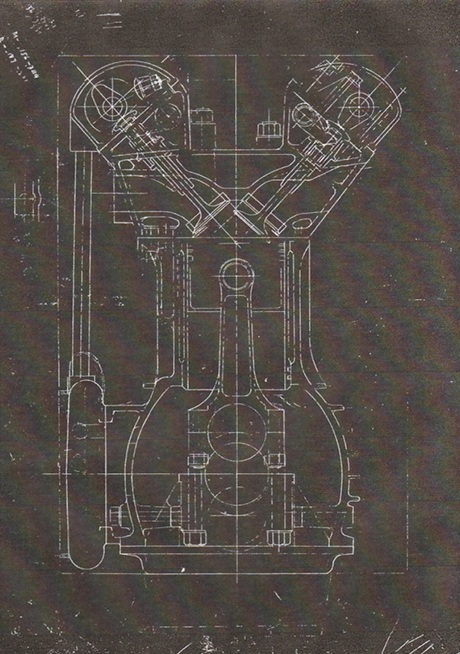
Scarab Grand Prix Engine Cross Section (early desmodromic valve design)
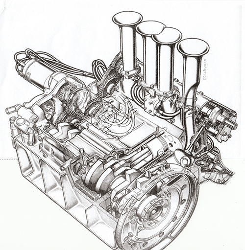
Scarab Grand Prix Engine as raced
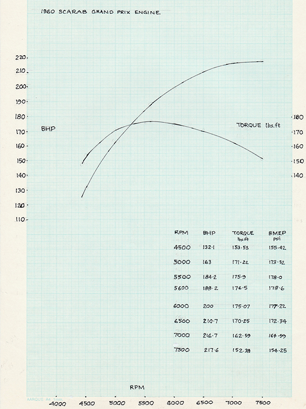
Scarab Grand Prix Engine power and torque curve
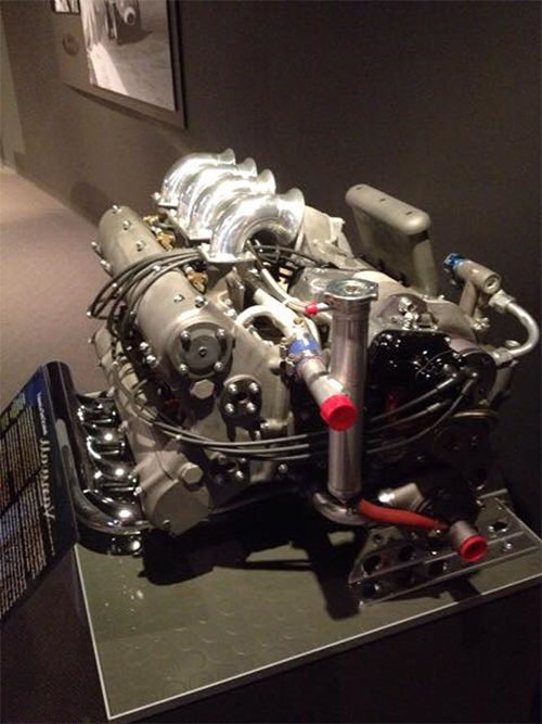
Restored Scarab Grand Prix Engine
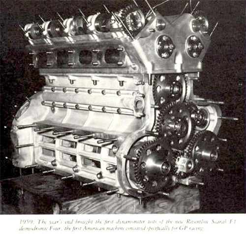
Scarab Grand Prix Engine in 1959